Push–pull output

A Class B push–pull output driver using a pair of complementary PNP and NPN bipolar junction transistors configured as emitter followers

A push–pull amplifier is a type of electronic circuit that uses a pair of active devices that alternately supply current to, or absorb current from, a connected load. This kind of amplifier can enhance both the load capacity and switching speed.

Push–pull outputs are present in TTL and CMOS digital logic circuits and in some types of amplifiers, and are usually realized by a complementary pair of transistors, one dissipating or sinking current from the load to ground or a negative power supply, and the other supplying or sourcing current to the load from a positive power supply.

A push–pull amplifier is more efficient than a single-ended "class-A" amplifier. The output power that can be achieved is higher than the continuous dissipation rating of either transistor or tube used alone and increases the power available for a given supply voltage. Symmetrical construction of the two sides of the amplifier means that even-order harmonics are cancelled, which can reduce distortion.[1] DC current is cancelled in the output, allowing a smaller output transformer to be used than in a single-ended amplifier. However, the push–pull amplifier requires a phase-splitting component that adds complexity and cost to the system; use of center-tapped transformers for input and output is a common technique but adds weight and restricts performance. If the two parts of the amplifier do not have identical characteristics, distortion can be introduced as the two halves of the input waveform are amplified unequally. Crossover distortion can be created near the zero point of each cycle as one device is cut off and the other device enters its active region.

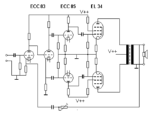
Schematic diagram of vacuum-tube amplifier
A vacuum tube amplifier often used a center-tapped output transformer to combine the outputs of tubes connected in push–pull.
Transformer coupled vacuum tube push-pull audio amplifier from 1924. The two triode output tubes are on right.
A Magnavox stereo tube push–pull amplifier, circa 1960, utilizes two 6BQ5 output tubes per channel. The two pairs of push-pull tubes are visible in front of the output transformers.

Push–pull circuits are widely used in many amplifier output stages. A pair of audion tubes connected in push–pull is described in Edwin H. Colpitts' US patent 1137384 granted in 1915, although the patent does not specifically claim the push–pull connection.[2] The technique was well known at that time [3] and the principle had been claimed in an 1895 patent predating electronic amplifiers.[4] Possibly the first commercial product using a push–pull amplifier was the RCA Balanced amplifier released in 1924 for use with their Radiola III regenerative broadcast receiver.[5] By using a pair of low-power vacuum tubes in push–pull configuration, the amplifier allowed the use of a loudspeaker instead of headphones, while providing acceptable battery life with low standby power consumption.[6] The technique continues to be used in audio, radio frequency, digital and power electronics systems today.

Digital circuits

Circuit of TTL NAND gate has a 'totem pole output' stage (right) consisting of two NPN transistors in push pull. When at least one of the inputs is low, transistor V1 is turned on, V2 is turned off, V3 is turned on and V4 off, pulling output voltage high. When both inputs are high, V2 is on, V3 is off and V4 is turned on, pulling output low.

A digital use of a push–pull configuration is the output of TTL and related families. The upper transistor is functioning as an active pull-up, in linear mode, while the lower transistor works digitally. For this reason they are not capable of sourcing as much current as they can sink (typically 20 times less). Because of the way these circuits are drawn schematically, with two transistors stacked vertically, normally with a level shifting diode in between, they are called "totem pole" outputs.

A disadvantage of simple push–pull outputs is that two or more of them cannot be connected together, because if one tried to pull while another tried to push, the transistors could be damaged. To avoid this restriction, some push–pull outputs have a third state in which both transistors are switched off. In this state, the output is said to be floating (or, to use a proprietary term, tri-stated).

An alternative to push–pull output is a single switch that disconnects or connects the load to ground (called an open collector or open drain output), or a single switch that disconnects or connects the load to the power supply (called an open-emitter or open-source output).

Analog circuits

A conventional amplifier stage which is not push–pull is sometimes called single-ended to distinguish it from a push–pull circuit.

In analog push–pull power amplifiers the two output devices operate in antiphase (i.e. 180° apart). The two antiphase outputs are connected to the load in a way that causes the signal outputs to be added, but distortion components due to non-linearity in the output devices to be subtracted from each other; if the non-linearity of both output devices is similar, distortion is much reduced. Symmetrical push–pull circuits must cancel even order harmonics, like 2f, 4f, 6f and therefore promote odd order harmonics, like f, 3f, 5f when driven into the nonlinear range.

A push–pull amplifier produces less distortion than a single-ended one. This allows a class-A or AB push–pull amplifier to have less distortion for the same power as the same devices used in single-ended configuration. Distortion can occur at the moment the outputs switch: the "hand-off" is not perfect. This is called crossover distortion. Class AB and class B dissipate less power for the same output than class A; general distortion can be kept low by negative feedback, and crossover distortion can be reduced by adding a 'bias current' to smoothen the hand-off.

A class-B push–pull amplifier is more efficient than a class-A power amplifier because each output device amplifies only half the output waveform and is cut off during the opposite half. It can be shown that the theoretical full power efficiency (AC power in load compared to DC power consumed) of a push–pull stage is approximately 78.5%. This compares with a class-A amplifier which has efficiency of 25% if directly driving the load and no more than 50% for a transformer coupled output.[7] A push–pull amplifier draws little power with zero signal, compared to a class-A amplifier that draws constant power. Power dissipation in the output devices is roughly one-fifth of the output power rating of the amplifier.[7] A class-A amplifier, by contrast, must use a device capable of dissipating several times the output power.

The output of the amplifier may be direct-coupled to the load, coupled by a transformer, or connected through a dc blocking capacitor. Where both positive and negative power supplies are used, the load can be returned to the midpoint (ground) of the power supplies. A transformer allows a single polarity power supply to be used, but limits the low-frequency response of the amplifier. Similarly, with a single power supply, a capacitor can be used to block the DC level at the output of the amplifier.[8]

Where bipolar junction transistors are used, the bias network must compensate for the negative temperature coefficient of the transistors' base to emitter voltage. This can be done by including a small value resistor between emitter and output. Also, the driving circuit can have silicon diodes mounted in thermal contact with the output transistors to provide compensation.

Push–pull transistor output stages

Typical transistor output stage of one channel of a 65 watt stereo amplifier from 1993. The 2 MOSFET push-pull output transistors (FET2, FET4) are bolted to the black heat sink. They are driven by transistors Q2, Q5, Q6, and Q7

Categories include:

Transformer-output transistor power amplifiers

It is now very rare to use output transformers with transistor amplifiers, although such amplifiers offer the best opportunity for matching the output devices (with only PNP or only NPN devices required).

Totem pole push–pull output stages

Two matched transistors of the same polarity can be arranged to supply opposite halves of each cycle without the need for an output transformer, although in doing so the driver circuit often is asymmetric and one transistor will be used in a common-emitter configuration while the other is used as an emitter follower. This arrangement is less used today than during the 1970s; it can be implemented with few transistors (not so important today) but is relatively difficult to balance and to keep a low distortion.

Symmetrical push–pull

Each half of the output pair "mirror" the other, in that an NPN (or N-Channel FET) device in one half will be matched by a PNP (or P-Channel FET) in the other. This type of arrangement tends to give lower distortion than quasi-symmetric stages because even harmonics are cancelled more effectively with greater symmetry.

Quasi-symmetrical push–pull

In the past when good quality PNP complements for high power NPN silicon transistors were limited, a workaround was to use identical NPN output devices, but fed from complementary PNP and NPN driver circuits in such a way that the combination was close to being symmetrical (but never as good as having symmetry throughout). Distortion due to mismatched gain on each half of the cycle could be a significant problem.

Super-symmetric output stages

Employing some duplication in the whole driver circuit, to allow symmetrical drive circuits can improve matching further, although driver asymmetry is a small fraction of the distortion generating process. Using a bridge-tied load arrangement allows a much greater degree of matching between positive and negative halves, compensating for the inevitable small differences between NPN and PNP devices.

Square-law push–pull

The output devices, usually MOSFETs or vacuum tubes, are configured so that their square-law transfer characteristics (that generate second-harmonic distortion if used in a single-ended circuit) cancel distortion to a large extent. That is, as one transistor's gate-source voltage increases, the drive to the other device is reduced by the same amount and the drain (or plate) current change in the second device approximately corrects for the non-linearity in the increase of the first.[9]

Push–pull tube (valve) output stages

Vacuum tubes (valves) are not available in complementary types (as are PNP/NPN transistors), so the tube push–pull amplifier has a pair of identical output tubes or groups of tubes with the control grids driven in antiphase. These tubes drive current through the two halves of the primary winding of a center-tapped output transformer. Signal currents add, while the distortion signals due to the non-linear characteristic curves of the tubes subtract. These amplifiers were first designed long before the development of solid-state electronic devices; they are still in use by both audiophiles and musicians who consider them to sound better.

Vacuum tube push–pull amplifiers usually use an output transformer, although Output-transformerless (OTL) tube stages exist (such as the SEPP/SRPP and the White Cathode Follower below).[citation needed] The phase-splitter stage is usually another vacuum tube but a transformer with a center-tapped secondary winding was occasionally used in some designs. Because these are essentially square-law devices, the comments regarding distortion cancellation mentioned above apply to most push–pull tube designs when operated in class A (i.e. neither device is driven to its non-conducting state).

A Single Ended Push–Pull (SEPP, SRPP or mu-follower[10]) output stage, originally called the Series-Balanced amplifier (US patent 2,310,342, Feb 1943). is similar to a totem-pole arrangement for transistors in that two devices are in series between the power supply rails, but the input drive goes only to one of the devices, the bottom one of the pair; hence the (seemingly contradictory) Single-Ended description. The output is taken from the cathode of the top (not directly driven) device, which acts part way between a constant current source and a cathode follower but receiving some drive from the plate (anode) circuit of the bottom device. The drive to each tube therefore might not be equal, but the circuit tends to keep the current through the bottom device somewhat constant throughout the signal, increasing the power gain and reducing distortion compared with a true single-tube single-ended output stage.

The transformer-less circuit with two tetrode tubes dates back to 1933: "THE USE OF A VACUUM TUBE AS A PLATE-FEED IMPEDANCE." by J.W.Horton in the Journal of the Franklin Institute 1933 volume 216 Issue 6

The White Cathode Follower (Patent 2,358,428, Sep. 1944 by E. L. C. White) is similar to the SEPP design above, but the signal input is to the top tube, acting as a cathode follower, but one where the bottom tube (in common cathode configuration) if fed (usually via a step-up transformer) from the current in the plate (anode) of the top device. It essentially reverses the roles of the two devices in SEPP. The bottom tube acts part way between a constant current sink and an equal partner in the push–pull workload. Again, the drive to each tube therefore might not be equal.

Transistor versions of the SEPP and White follower do exist, but are rare.

Ultra-linear push–pull

A so-called ultra-linear push–pull amplifier uses either pentodes or tetrodes with their screen grid fed from a percentage of the primary voltage on the output transformer. This gives efficiency and distortion that is a good compromise between triode (or triode-strapped) power amplifier circuits and conventional pentode or tetrode output circuits where the screen is fed from a relatively constant voltage source.

See also

References

  1. ^ Joe Carr, RF Components and Circuits, Newnes, page 84
  2. ^ Donald Monroe McNicol, Radios' Conquest of Space: The Experimental Rise in Radio Communication Taylor & Francis, 1946 page 348
  3. ^ http://www.leagle.com/xmlResult.aspx?page=5&xmldoc=193278360F2d723_1537.xml&docbase=CSLWAR1-1950-1985&SizeDisp=7 WESTERN ELECTRIC CO. v. WALLERSTEIN retrieved 12/12/12
  4. ^ US Patent 549,477 Local Transmitter Circuit for Telephones., W. W. Dean
  5. ^ Radios - RCA Radiola Balanced Amplifier 1924
  6. ^ Gregory Malanowski The Race for Wireless: How Radio Was Invented (or Discovered?), AuthorHouse, 2011 ISBN 1463437501 pages 66-67, page 144
  7. ^ a b Maurice Yunik Design of Modern Transistor Circuits, Prentice-Hall 1973 ISBN 0-13-201285-5 pp. 340-353
  8. ^ Donald G. Fink, ed. Electronics Engineer's Handbook, McGraw Hill 1975 ISBN 978-0-07-020980-0 pp. 13-23 through 13-24
  9. ^ Ian Hegglun. "Practical Square-law Class-A Amplifier Design". Linear Audio. 1.
  10. ^ "SRPP Decoded". The Tube CAD Journal. Retrieved 7 November 2016.

Read other articles:

Polytechnic in Ibadan, Nigeria The Polytechnic, IbadanIse loogun iseTypePublic polytechnicEstablished1970RectorProf. Kazeem A. AdebiyiLocationIbadan, NigeriaCampusUrbanWebsitewww.polyibadan.edu.ng The Polytechnic, Ibadan Entrance Gate The Polytechnic, Ibadan Exit Gate The Polytechnic, Ibadan The Polytechnic, Ibadan (also called Poly Ibadan) is an institution of higher learning in Ibadan in Oyo State, Nigeria.[1] Founded on August 1970, Poly Ibadan is similar to other polytechnics in N...


Ketua Komisi Militer Pusat Partai Komunis Tiongkok中国共产党中央军事委员会主席Lambang Partai Komunis TiongkokPetahanaXi Jinpingsejak 15 November 2012KantorGedung 1 Agustus (de jure), BeijingDitunjuk olehKomite Sentral Partai Komunis TiongkokMasa jabatanLima tahun, tidak ada batasan jangka waktuPejabat perdanaMao ZedongDibentuk1945; 1954WakilWakil Ketua Komisi Militer PusatSitus webChairmanship Ketua Komisi Militer Pusat Republik Rakyat Tiongkok中华人民共和国中央军...


Yearly conference held for climate change treaty negotiations 2023 United Nations Climate Change ConferenceLogoA group photo of national leaders and other dignitaries at the 2023 United Nations Climate Change ConferenceNative name مؤتمر الأمم المتحدة للتغير المناخي 2023Date30 November – 13 December 2023 (2023-11-30 – 2023-12-13)LocationExpo City, Dubai, United Arab EmiratesOrganised byUnited Arab EmiratesParticipantsUNFCCC m...

  البرمجيات في المصلحة العامة البرمجيات في المصلحة العامة‌ البلد الولايات المتحدة  المقر الرئيسي نيويورك  تاريخ التأسيس 16 يونيو 1997[1]  الرئيس دايل جاربي (1 أغسطس 2006–11 أغسطس 2016)[2]مارتن متشلنير (11 أغسطس 2016–13 أغسطس 2018)[3]  المالية إجمالي الإيرادات 635312 �...


العلاقات الإيطالية البوتانية إيطاليا بوتان   إيطاليا   بوتان تعديل مصدري - تعديل   العلاقات الإيطالية البوتانية هي العلاقات الثنائية التي تجمع بين إيطاليا وبوتان.[1][2][3][4][5] مقارنة بين البلدين هذه مقارنة عامة ومرجعية للدولتين: وجه المقارنة...


Régionalisation indicative du rapport Europe 2000 + : Centre des capitales Nouveaux Länder allemands Arc alpin Diagonale continentale Arc latin Méditerranée centrale Arc atlantique Régions de la mer du Nord Arc baltique Le centre des capitales est un espace décrit par la Commission européenne dans le rapport Coopération pour l’aménagement du territoire européen - Europe 2000 Plus[1]. Dans cet espace se trouve le siège de la plupart des institutions de l'Union européenne. Le...

Wildlife refuge in Merced County, California San Luis National Wildlife RefugeIUCN category IV (habitat/species management area)North levee, San Luis Refuge - March, 2007Map of the United StatesLocationMerced County, California, United StatesNearest cityLos Banos, CaliforniaCoordinates37°12′00″N 120°48′04″W / 37.19994°N 120.80103°W / 37.19994; -120.80103[1]Area26,600 acres (108 km2)Established1966Governing bodyU.S. Fish and Wildlife S...


United States historic placeCooper Library in Johnson ParkU.S. National Register of Historic PlacesNew Jersey Register of Historic Places Show map of Camden County, New JerseyShow map of New JerseyShow map of the United StatesLocation2nd and Cooper Streets, Camden, New JerseyCoordinates39°56′53″N 75°7′31″W / 39.94806°N 75.12528°W / 39.94806; -75.12528Area2.5 acres (1.0 ha)Built1916 (1916)ArchitectWalter Karcher; Livingston SmithArchitectural ...


جيرارد فيليب   معلومات شخصية اسم الولادة (بالفرنسية: Gérard Philip)‏  الميلاد 4 ديسمبر 1922 [1][2][3][4][5][6][7]  كان  الوفاة 25 نوفمبر 1959 (36 سنة) [1][2][3][4][5][6][7]  باريس[1]  سبب الوفاة سرطان الكبد  مواطنة فرنسا  ع�...

Questa voce o sezione sull'argomento motori automobilistici non cita le fonti necessarie o quelle presenti sono insufficienti. Puoi migliorare questa voce aggiungendo citazioni da fonti attendibili secondo le linee guida sull'uso delle fonti. Lancia V6Descrizione generaleCostruttoreLancia Tipomotore a V Numero di cilindri6 Alimentazionebenzina Schema impiantoDistribuzione2 valvole per cilindro CombustioneRaffreddamentoa liquido NoteCostruzione in lega di alluminio voci di motori present...


Muga silkworms on a som tree Wild silks have been known and used in many countries from early times, although the scale of production is far smaller than that from cultivated silkworms. Silk cocoons and nests often resemble paper or cloth, and their use has arisen independently in many societies.[1] Background Silk taken from various species has been used since ancient times, either in its natural state or after some form of preparation. Spider webs were used as a wound dressing in an...


Évolution de la température lors de la solidification d'un eutectique. Un eutectique (du grec εὔτηκτος -eútēktos- : qui fond aisément) est un mélange de deux ou plusieurs corps purs qui fondent et se solidifient à température constante de manière uniforme, contrairement aux mélanges habituels où le changement de température conduit à une variation de la proportion de solide par rapport à celle de liquide. Il se comporte en fait comme un corps pur du point de vue de...

1906 book by Rudyard Kipling Tree Song redirects here. For the John Williams album, see John Williams discography. This article needs additional citations for verification. Please help improve this article by adding citations to reliable sources. Unsourced material may be challenged and removed.Find sources: Puck of Pook's Hill – news · newspapers · books · scholar · JSTOR (September 2013) (Learn how and when to remove this message) First American edit...



Overview of the environmental issues in CanadaEnvironmental issues in Canada include impacts of climate change, air and water pollution, mining, logging, and the degradation of natural habitats. As one of the world's significant emitters of greenhouse gasses,[1] Canada has the potential to make contributions to curbing climate change with its environmental policies and conservation efforts. Climate change Main article: Climate change in Canada This section is an excerpt from Climate c...


Апостолівський район ліквідована адміністративно-територіальна одиниця Герб Прапор Колишній район на карті Дніпропетровська область Основні дані Країна: СРСР ( УСРР),  Україна Область: Дніпропетровська область Код КОАТУУ: 1220300000 Утворений: 1923 рік Ліквідований: 17 л�...

American historian, Navy officer (1887–1976) Samuel Eliot MorisonMorison in 1953Born(1887-07-09)July 9, 1887Boston, Massachusetts, U.S.DiedMay 15, 1976(1976-05-15) (aged 88)Boston, Massachusetts, U.S.AllegianceUnited StatesService/branchUnited States NavyYears of service1942–1951RankRear admiral (reserve)Battles/warsWorld War IIAlma materHarvard UniversitySciences Po Samuel Eliot Morison (July 9, 1887 – May 15, 1976) was an American historian noted for his works of maritime hi...


Сантьяго Ланхеангл. Santiago Raúl Lange Гражданство  Аргентина Дата рождения 22 сентября 1961(1961-09-22) (62 года) Место рождения Сан-Исидро, Аргентина Рост 1,84 м Вес 73 кг Профессия инженер-кораблестроитель Карьера Класс Накра 17, Торнадо, Снайп, Лазер Клуб Club Náutico San Isidro Колледж С...


För den gamla Olympiastadion, se Tokyos Olympiastadion (1958). Tokyos Olympiastadion Officiellt namn新国立競技場Placering10-2 Kasumigaoka-machi, Shinjuku-ku, TokyoNärmaste hållplatsKokuritsu-Kyōgijō station (Ōedo-linjen)Sendagaya station & Shinanomachi station (Chūō-Sōbu-linjen)Kapacitet68 000Byggkostnad¥149 miljarderArkitektKengo KumaEntreprenörTaisei Corporation Större evenemangOlympiska sommarspelen 2020Paralympiska sommarspelen 2020Datu...

List of events in the year 1123 ← 1122 1121 1120 1119 1118 1123 in Ireland → 1124 1125 1126 1127 1128 Centuries: 11th 12th 13th 14th Decades: 1100s 1110s 1120s 1130s 1140s See also:Other events of 1123 List of years in Ireland Events from the year 1123 in Ireland. Incumbents High King of Ireland: Toirdelbach Ua Conchobair Events Maollosa O'Conchubhair receives the Cross of Cong[1] References ^ Illustrated Dictionary of Irish History. Mac Annaidh, S (ed). Gill and Macmilla...


AwardMarumo Medal, Class ITypeMilitary decoration for meritCountry BophuthatswanaPresented bythe State PresidentStatusDiscontinued in 1994Established1988Ribbon bar BDF pre-1994 & SANDF post-2002 orders of wearNext (higher)BDF precedence: Defence Force Merit Medal SANDF precedence: Sandile Medal Next (lower)BDF succession: Defence Force Commendation Medal SANDF succession: Merit Medal in Silver The Marumo Medal, Class I was instituted by the State President of the Republic of Bo...